Analog video signal is a very important part of FPV yet little is posted about it. I'm writing this article in hope to shed some light on how the camera's image is transformed into an electrical signal and the other way around. I'll describe the basic black and white composite video signal. "Composite" because it contains separate parts:
- The camera signal which contain the picture information.
- Synchronizing pulses so the display device can properly reconstruct the image.
- Blanking pulses to hide parts of the signal you don't want to see on the screen.
The camera signal
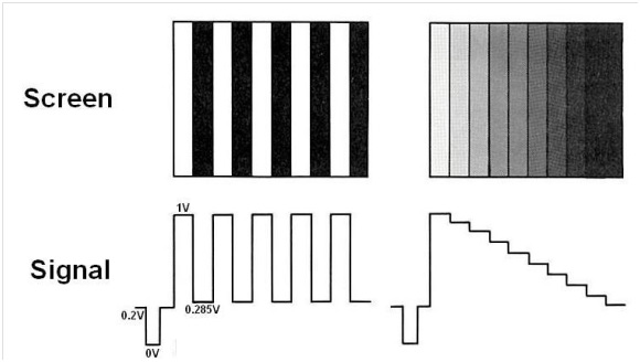
A typical video signal move from 0 to 1V. 1V being white and 0.285V being black, the part between 0V and 0.285V is used for other thing than the image itself. Now imagine a line being drawn on a TV screen starting from top left corner moving right. You want a white line? Apply a 1V signal. You want a black line? Apply a 0.285V signal, of course every shades of grey are in between. You want half the lines white and the other black? Apply 1V for half the time and 0.285V for the other half.
Effect of video signal amplitude on tint:
 Synchronizing pulses and blanking pulses
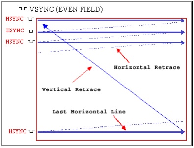
The time a line is drawn is about 53-54 micro second or 0.000053s, much too fast for your eye to notice. What happen you reach the end of line? A blanking pulse (0.2V) make the line invisible then a sync pulse (0.0V) tells to go down two lines and start again at the screen’s left side. This process repeat over and over until all odd lines (1,3,5,7...) are drawn and it reached the bottom of the screen. Now a series of sync pulses tell the display device to start on top and draw the even lines (2,4,6,8...) So during 1/60sec all odd lines are drawn and another 1/60 the even lines appear, effectively making 30 images/sec. This is how your video goggle reconstructs the image from the video signal produced by the camera and broadcasted by your wireless video feed.
How lines are traced on your video screen:
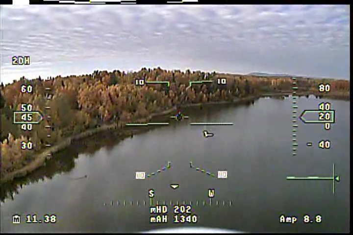
The picture below is a screen grab from an FPV-japan DVR which record the whole picture. You can see a black bar at the right-most side, this is the horizontal sync pulse. At the bottom and top, there's another black bar, this is the vertical sync. Note that, in this case, some space of the vertical sync is populated by a dynamic white bar code, this is eagletree systems's telemetry data.
The composite video signal is easily disturbed by voltage fluctuation. As a line is being drawn, if an unwanted change in voltage occur, you’ll see a change in tint on the screen where it happened. As when you draw something and someone bump your arm. If this happen over and over (like the pulsing of a switch mode BEC, you may see a localized change in tint on every horizontals lines. Since the pulsing is not following the horizontal retrace at the exact same pace, a diagonal or vertical lines pattern appear on your screen. By counting the number of diagonal lines you see and multiplying by 15750 (number of lines drawn in one second) you’ll find the beat frequency of the interfering device. For example; you see 25 lines on screen (25*15750=393750hz or 400khz). This beat frequency is often found in small switch mode power supply. An ESC for example, beat much slower at around 8 or 9 khz. Those beasts create horizontal lines patterns because they beat slower than the horizontal retrace rhythm of 15750hz, sparing some lines of change in tint. This time you may multiply the number of horizontal lines by 60 to know the beat frequency of the interfering device. In short, diagonal/vertical lines patterns are caused by small noisy electronic devices and horizontal pattern by bigger electronics, ESC most often.
Example of fine diagonal lines produced by a fast beating device:
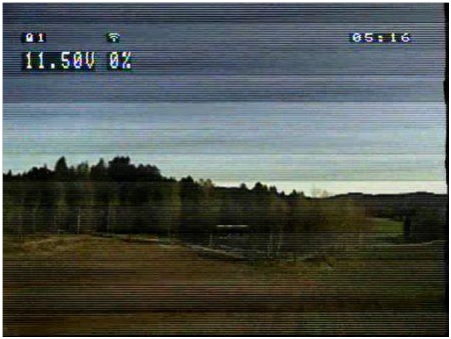
 Example of large horizontal lines created by a slow beating device:
Hugo Chamberland, TrueRC Canada inc.